


How does a low noise amplifier work?
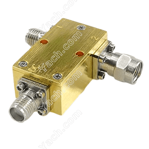
 Low noise amplifier (LNA) for short is mainly used to amplify the received small signal at the receiving end of the mobile phone base station.
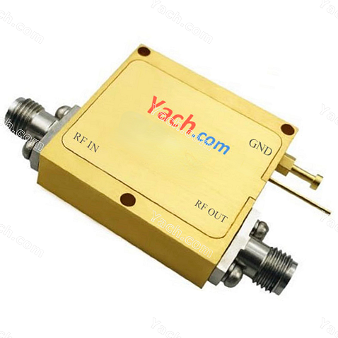
The signal at the input end first filters out the out of band signal through the filter circuit. Then, the signal is divided into two equal parts by an on-off circuit, and then amplified for the first time by a triode circuit. The amplified signal is then combined into one circuit through the on-off circuit. Then the signal passes through an attenuation circuit to reduce the influence of noise. After that, the signal amplification is completed through the primary amplification circuit. Finally, the signal is divided into four equal parts for output through the two pole separation circuit.
On the difference between LNA and the "high frequency amplifier"
In fact, high-frequency amplifier is a very broad concept, which can be divided into many types, and LNA is one of them. But the high-frequency amplifier usually refers to the high-frequency power amplifier. LNA is used in the receiving circuit of the mobile phone base station to amplify the received signal. Therefore, it has high requirements for noise suppression and low power consumption. The high-frequency power amplifier is used in the transmitter of the base station to greatly amplify the transmitted signal, or applied in some other fields. It has a wide range of applications. Generally, it has low noise suppression requirements and high power consumption.
Description of main technical parameters of amplifier:
Operating frequency range:
It refers to the operating frequency range within which the amplifier meets all levels of indicators. The actual operating frequency range of the amplifier may be greater than the defined operating frequency range.
Power gain (g):
It refers to the ratio between the output power and input power of the amplifier. The unit is usually "DB".
Gain flatness( Δ G) :
It refers to the range of amplifier gain change within the whole operating frequency range at a certain temperature.
Noise figure (NF):
 Noise figure refers to the ratio of the signal-to-noise ratio at the input end to the signal-to-noise ratio at the output end of the amplifier. The unit is usually "DB".
The noise coefficient is expressed by the following formula: nf=10lg (input SNR / output SNR)
When the noise figure of the amplifier is relatively low (for example, nf<1), the noise figure of the amplifier is usually expressed by the noise temperature (T).
1 dB compression point output power (p1db):
The amplifier has a linear dynamic range in which the output power of the amplifier increases linearly with the input power. This amplifier is called a linear amplifier, and the ratio of the two powers is the power gain G. As the input power continues to increase, the amplifier enters the nonlinear region, and its output power no longer increases linearly with the increase of input power, that is, its output power is lower than the expected value of small signal gain. Generally, the output power value when the gain drops to 1dB lower than the linear gain is defined as the 1dB compression point of the output power, represented by p1db.
Third order cut-off point (IP3):
 The simplest way to measure the nonlinear characteristics of the amplifier is to measure the power level p1db at the 1dB compression point. Another popular method is to use two adjacent signals 5 to 10MHz apart. When the two signals with frequencies F1 and F2 are added to an amplifier, the output of the amplifier contains not only the two signals, but also the intermodulation component (IM) with frequency mf1+nf2. Here, m+n is the order of the intermodulation component. At the medium saturation level, the third-order component closest to the pitch frequency usually dominates.
Since the third-order term plays a dominant role up to the point with serious distortion, the third-order cut-off point (IP3) is often used to characterize intermodulation distortion (see Figure 3). The third-order cut-off point is an important index to describe the linearity of an amplifier. The typical value of the third-order cutoff power is 10-12db higher than p1db. IP3 can be obtained by measuring IM3, and the calculation formula is:
Ip3=pscl+im3/2;
PSCL - single carrier power; If the third-order intermodulation point is known, the fundamental and third-order intermodulation rejection ratio and the stray level of the third-order intermodulation point can be estimated by the following formula:
Fundamental and third-order intermodulation rejection ratio =2[ip3- (pin+g)]
Third order intermodulation spurious level =3 (pin+g) -2ip3
Operating voltage / current:
It refers to the power supply voltage to be supplied when the amplifier works and the current value to be supplied when the amplifier works.
Definition of amplifier gain window:
 In this product manual, the gain definition of amplifier adopts the definition method of gain window (excluding narrowband power amplifier). The gain window is defined according to the maximum gain allowed by the amplifier (Gmax), the minimum gain allowed by the amplifier (gmin), and the gain fluctuation of the amplifier( Δ G) These three gain indexes clearly define the allowable fluctuation and variation range of the amplifier gain.
Expressed by the following formula:
VSWR = (1+| Γ|)/ (1-| Γ|);
among Γ= (z-z0) / (z+z0)
VSWR: input output voltage standing wave ratio
Γ: reflection coefficient
Z: Actual impedance at the input or output of the amplifier
Zo: required system impedance
- 上一篇:Low Noise Amplifier LNA775141 [2022-05-31]
- 下一篇:PIN Diode Switches SW517224 [2022-05-30]